Starting in March 2020, I began a large stream project to model a comprehensive, highly-detailed Caterpillar 434E backhoe. Please watch the first stream (first 3 minutes of abridged version at least) for an overview.
It's a straight-forward project of building a complex model over an extended period of time. The spin on the project is that I want your help to accomplish it! If I build some parts and you build some parts, we will finish this thing much quicker. Plus the contribution format will include reviews, the potential of having your piece(s) assimilated into the final model. Not to mention large quantities of XP are at stake 🤑
NOTE: This is an involved project reserved for Citizen members.

The general idea is that I kickoff stages of the project via live stream, which is typically once per month. For the time in between streams, you choose a piece of the backhoe and apply what you learned from the stream to that piece. For example, the first stream covered initial block out. So between stream 1 and stream 2, your job is to pick a piece and block it out.
This is the repeating protocol for each Assignment Period (between-streams):
I will reply to this thread after each stream with a [big] assignment post denoted by a 📣 emoji in the title. There I will clarify instructions about each Assignment Period.
We will centralize our collaborative communication between the streams and this thread. Ask any and all questions pertaining to the Backhoe project here.
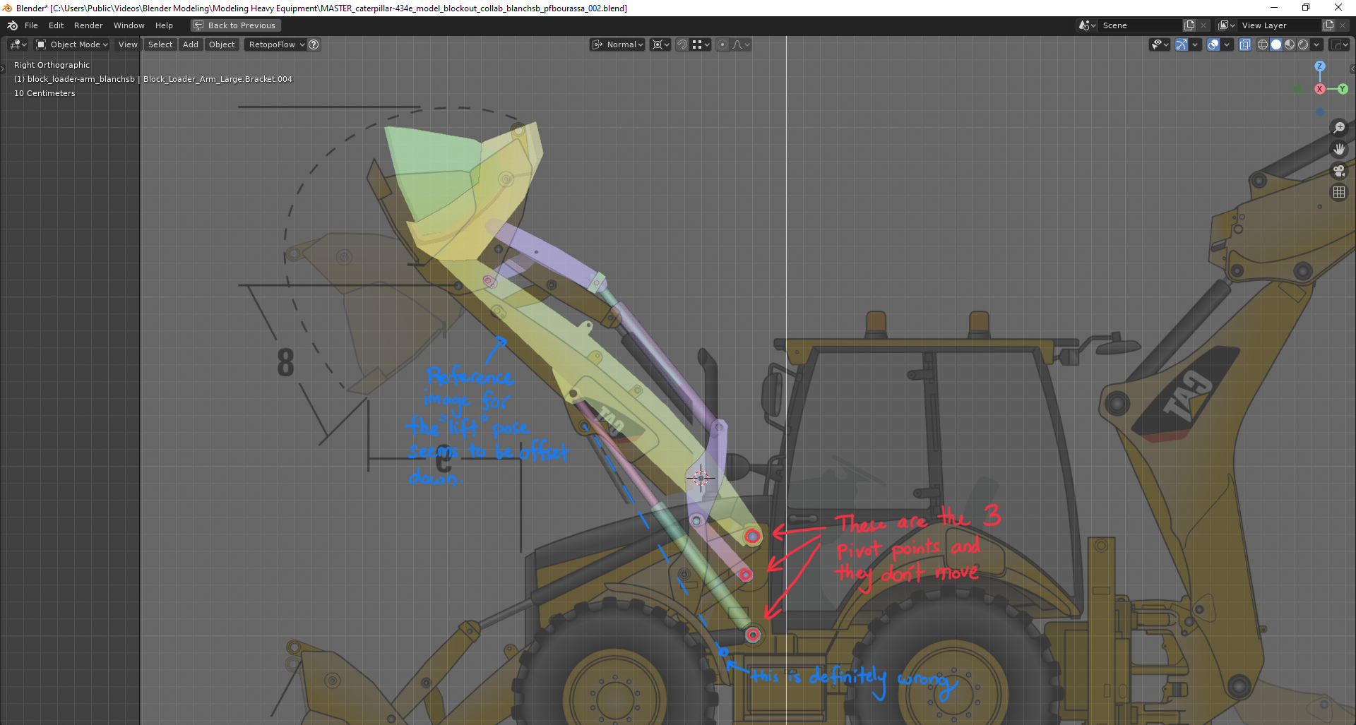
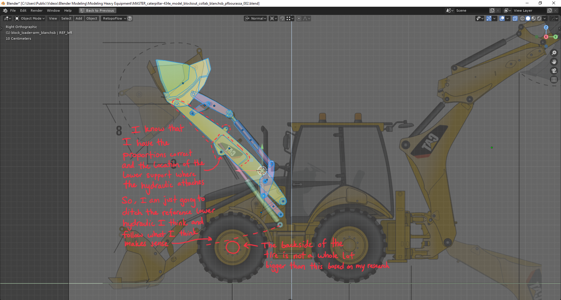
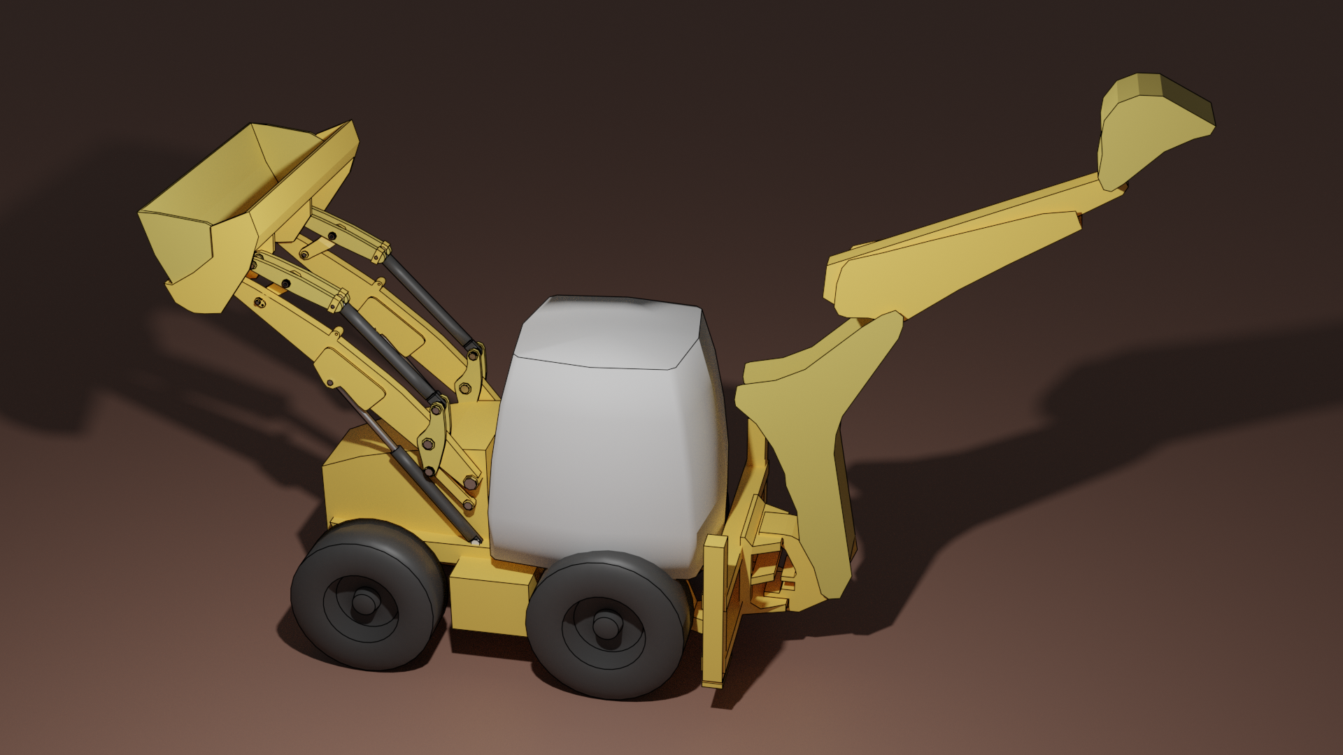
Ok I am hitting a decent snag where reality clashes with reference. I wanted to get some community feedback/critique on my thought process.
The lower hydraulic does not seem to fit based on the reference angle it is shown at
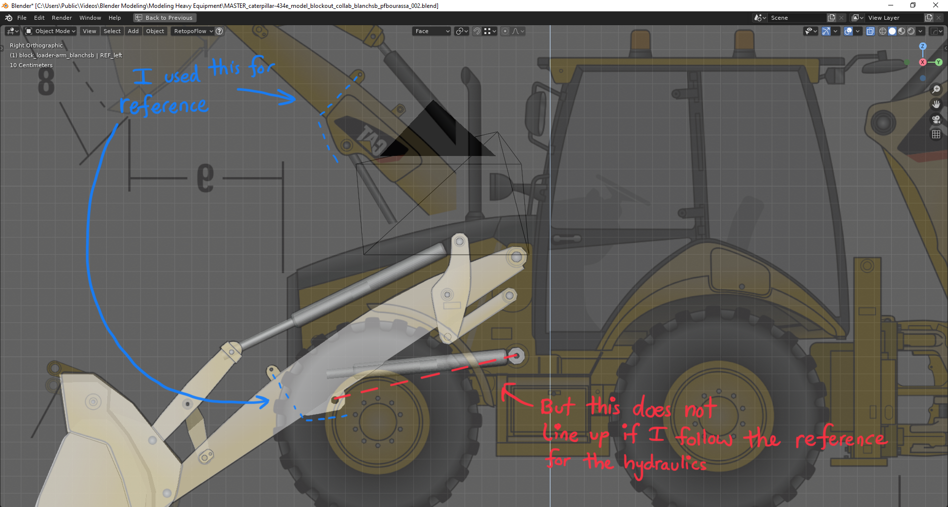
I know the proportions are correct because I rotated the main loader arm in order to figure out the location for the lower support and also using a common reference bracket for it’s location.
So, I just rotated everything and lined up to make sure I got close enough and I think I am going to push on with using the Red Dashed line (on the first image above) for where the hydraulic is supposed to go: My only concern is tire/wheel clearance where the main frame connects to the tire/wheel. Maybe I need to collaborate with ![]() spikeyxxx as well since he offered the wheels???
spikeyxxx as well since he offered the wheels???
I’m going this route I think. The lower support is about midway along the loader arm and that would make most sense for load-bearing support while it is cantilevered in the air holding a “load”
@theluthier ![]() blanchsb ppfbourassa
blanchsb ppfbourassa
As far as I can tell from the reference pictures, thos two, ugly, additional pieces on the loader bucket are on all the pictures and seem very functional to me, although I 'm not sure what they are doing, I read them sort of like this:
So they can be put in different positions...
![]() blanchsb Are you saying the piston doesn't seem to point at the part it needs to connect to in the drawing? If that's the case, I'd say to follow your intuition, it's probably just a mistake in the illustration.
blanchsb Are you saying the piston doesn't seem to point at the part it needs to connect to in the drawing? If that's the case, I'd say to follow your intuition, it's probably just a mistake in the illustration.
Or are you saying there isn't enough room between the tire and the body for it to fit? That's trickier, because it looks to me like you are on the right track.
![]() spikeyxxx My interpretation of this front area is that the base model has this rail going across so the user can add or modify the bucket to do any number things, and this particular reference has these metal bars attached because it's a function they needed.
spikeyxxx My interpretation of this front area is that the base model has this rail going across so the user can add or modify the bucket to do any number things, and this particular reference has these metal bars attached because it's a function they needed.
I could totally be wrong about this, but if they are added by an individual owner, I'd rather not include them in our model.
ppfbourassa You are probably right. I looked at some more reference online and did find pictures where there is nothing connected to that rail.
ppfbourassa yeah I am saying that it’s not pointing to the part it needs to connect to AND I’m a little concerned if I go with my gut and ditch the reference that the hydraulics will interfer on the back side of the wheel/tire where it connects to the axle
Gotcha,
For what it's worth, I think you are correct on where it should connect, and how thin the axle is.
Those things are forklifts attached to the bucket, you can see where they can pivot on the top. and they are hold down with bolt on down.
![]() blanchsb kudos on your functional research and testing. I agree with your inclination to follow the red dashed line reroute. I've run into a few things with the blueprint that I know are inaccurate to the real thing. I trust your testing results 👍
blanchsb kudos on your functional research and testing. I agree with your inclination to follow the red dashed line reroute. I've run into a few things with the blueprint that I know are inaccurate to the real thing. I trust your testing results 👍
Also I think I made the wrong call to omit the forklift brackets. All 4 official CAT brochures feature them. This is another strike against the blueprint's accuracy lol.
Thanks to ![]() spikeyxxx and
spikeyxxx and ![]() louhikarme for clearing up the mystery 👏
louhikarme for clearing up the mystery 👏
one thing i've learned when doing exact models of real things that blueprints are lacking, either because copyright stuff or that things have changed between different years of same manufacturer and then you also get reference pictures that might be on different model. So the more you have real reference pictures the better.
:)
![]() louhikarme there is also the little issue that what we get are usually not the actual blueprints (I mean the technical drawings) like the ones they use to manufacture something.
louhikarme there is also the little issue that what we get are usually not the actual blueprints (I mean the technical drawings) like the ones they use to manufacture something.
Anyway, a blueprint is just a copy of a drawing, so any drawing could be made in a blueprint. The naming is not incorrect, it just sounds more 'official' than it is.
They make a drawing on transparent paper and then lay that on top of special paper with a light sensitive layer (which is yellow, by the way), shine a bright light over it so only where the lines are on the drawing the yellow layer stays. and then they fixate those lines with ammonia, which turns them blue. Hence the name;)
This is also worth mentioning the differences between a concept drawing or blueprint and a technical source-controlled-engineer-approved-drawing.
Many sales catalogs fall short because they are built by Sales and Marketing departments. These departments don't interface on a daily basis with the engineering departments. So, naturally you get the "Silo" effect where one department posts stuff and then the other continues with trial and error development.
I agree with ![]() louhikarme. Those forks rotate forward about the pivot bar on the top and turn the bucket into a fork-lift hybrid. Notice the forks get thinner at the bottom and thicker at the top. Ease of "stabbing" design.
louhikarme. Those forks rotate forward about the pivot bar on the top and turn the bucket into a fork-lift hybrid. Notice the forks get thinner at the bottom and thicker at the top. Ease of "stabbing" design.
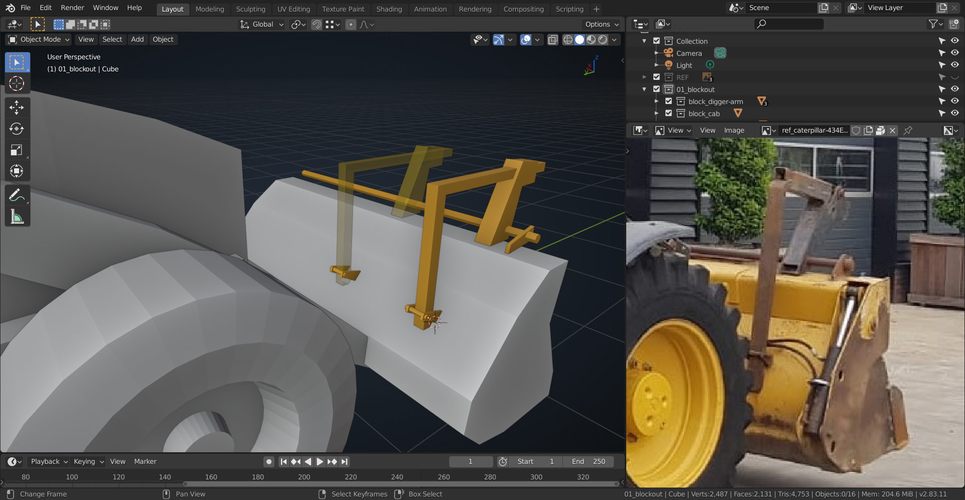
Okay. I feel like I am done with the basic block out. Maybe I have gone farther than expected or maybe this is just right. I’m hoping it is far enough Because I am ready to move on to train some more. I have most mirror modifiers still active but there are 40+ objects so I don’t remember if I applied a couple on the more basic shapes.
I’m including the wireframe and basic render here for feedback and critique. I tried my best to have clean topology to make it easy to add SubDiv Modifier(s) but there are probably areas that can be improved farther. There are a lot of circular cuts. I kept all circles at division of 8 and maintained same circle-rotation on pieces that shared a circle cutout.
If this looks good enough then I will upload it to the Google Sheet. Hope everyone else is having as much fun as I did! Go DOGs!
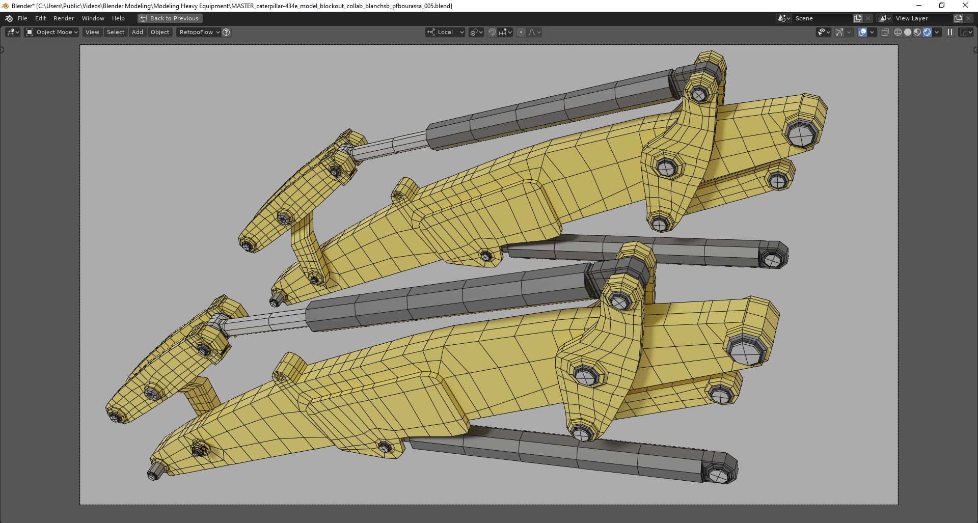 Wire Frame - Loader Arm Assembly
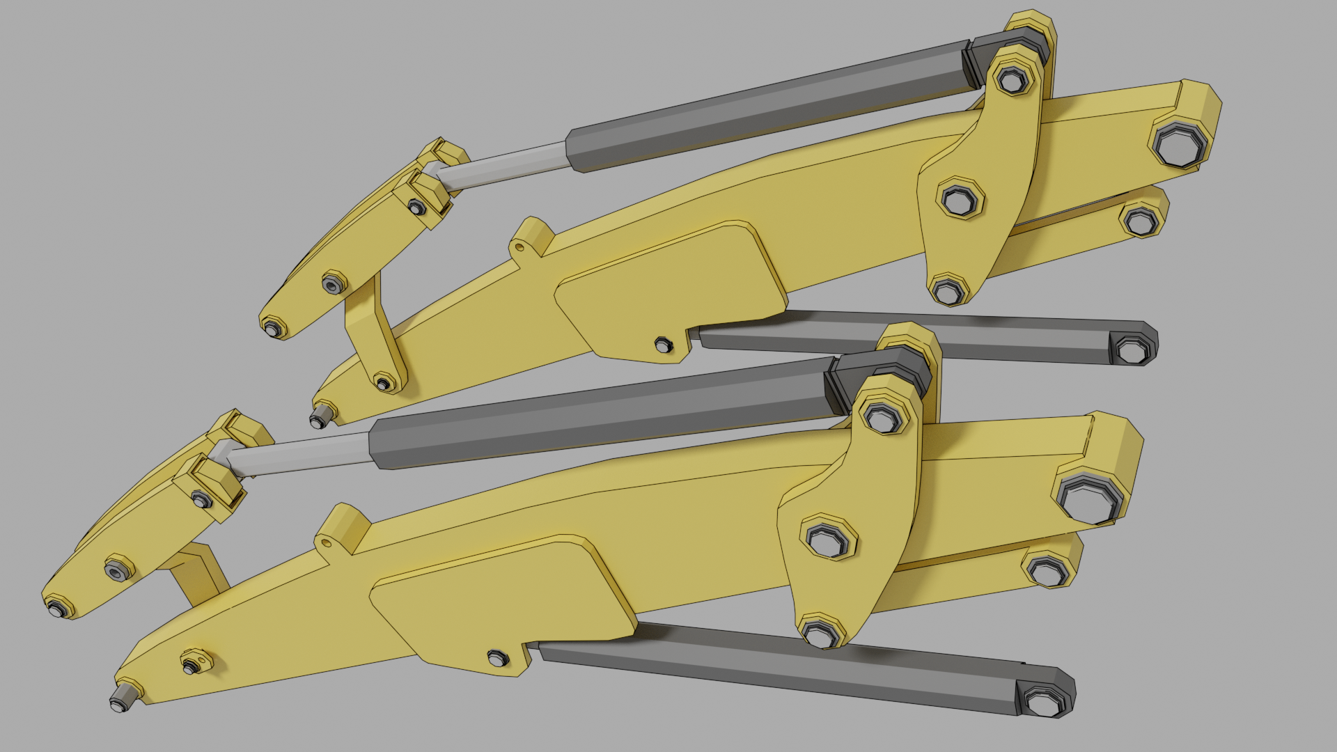 Block Out - Loader Arm Assembly
 Reference and Playing Around
Notice how the lower frame is cutting into the lower hydraulic. That will have to be thinned out to make room.
I checked out the similar CAT machine at my work and there is plenty of Front Axle clearance behind the Front Wheels. There’s not a ton going on back there so I think the lower hydraulic shouldn’t interfere.
ppfbourassa I’ll send you the updated file here shortly the same way I sent it before.
I posted the link via private message ppfbourassa but noticed that you already uploaded your to the Google Sheet. My bad.
@theluthier I added a comment on my ”Attemp” row for the Loader Arm. When you get a free chance, let me know if you are able to download it just fine.
![]() dostovel I just put the link on my ”Attempt” row’s comment section for the Google Sheet. Hopefully that should work for you too.
dostovel I just put the link on my ”Attempt” row’s comment section for the Google Sheet. Hopefully that should work for you too.
![]() blanchsb You've crushed the blockout stage 2. Even a little further than I expected. Excellent work translating and interpreting the drawing + photos. The intersection of hydraulic + chassis blockout is going to be one of many things we'll need to solve. Thanks for making a note of it! And thanks for kicking off the collaboration with a bang 🤜💥🤛
blanchsb You've crushed the blockout stage 2. Even a little further than I expected. Excellent work translating and interpreting the drawing + photos. The intersection of hydraulic + chassis blockout is going to be one of many things we'll need to solve. Thanks for making a note of it! And thanks for kicking off the collaboration with a bang 🤜💥🤛
PS: I'm able to download your file fine 👌