
hey guys, so I've been trying to get a light trail to follow a path and the values in the map range are confusing me.
basically I'm using an emissive principled bsdf shader with a gradient to get the effect. The x vector value is deciding where the light trail is at any given time and I want to use a map range node to tell it that it should start at 0 and end with 1 instead of -.55 and .55 or whatever it is now. so basically turning the value into a 0-100% bar. When I tried using the map range node with a combine xyz it just didnt work properly it started at like 0.05 and then ended at -0.08 and if I clamp it because of that it wont even go past the halfway point of the path.
Am I just using it wrong or completely using the wrong node I swear I've watched like 5 tutorials now on how to use it and still don't get it.
Also even when I controlled it by just keyframing the vector x location the line moved at a different pace than an object which is following the curve object this shader is on. just keyframing where it starts and ends with out ranging looks good but it keeps jumping ahead and falling behind i think cause of the vectoring being UV based.

Start and End point
What I'm trying to do (except I want to have the line matching the pace of the cyclinder)
Shader setup

Start Map Range
End Map range value

I could be wrong, but your from min is higher than your from max. If you need it to flow opposite direction I believe you need to swap the to min and max. As for your description of when you manually animate it, it sounds like you have an easing issue. Either change the handles to vector(v->vector) or change the F curve to linier. I don't remember the hotkey but I believe it's Ctrl+e. You can probably guess which method I prefer 🤗
Unfortunately neither idea worked. The map range node needed to be in that order to flow the correct way. I still dont get if was wrong in my use though cause all I want with that is to get it to change the values to 0 and 1 so I can just clamp it and have it complete the whole loop at 1.
Changing the easing and vector handles didn't work either unfortunately. they were already that way it seems 😔

Hi Sam,
The Min and Max in the MapRange Node are badly named. Min can be larger than Max. I always think of it as From A to A and From B to B.
In your upper Screenshot of your Nodes, for instance, your Input is 1.6:
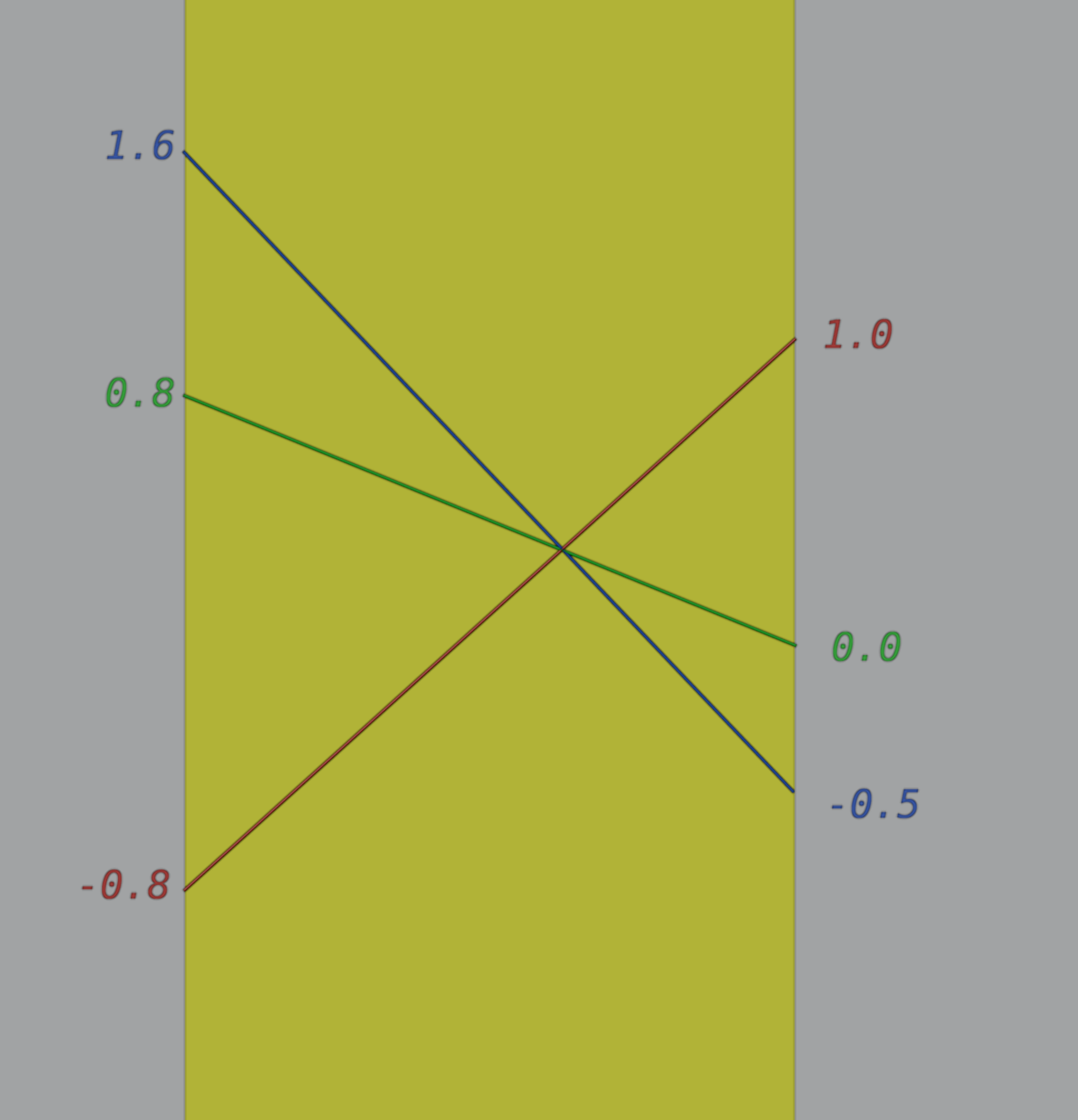
In the Map Range, you go from 0.8 to 0 and from -0.8 to 1. This means that the Input Value of 1.6 becomes and Output Value of -0.5.
(If you would turn on Clamp in the Map Range Node, that would be clamped to the [To Min, To Max] range, meaning it then would be 0.0)
The Color Ramp however Clamps its Input to a [0, 1] range, meaning -0.5 becomes 0.
OMG! I just now saw the video. I didn't even notice that the text "What I'm trying to do" is a link. Okay, the easiest way in my opinion would be to use dynamic paint. It's been awhile, I don't remember if it's called wetness or drying. Either way it's an option in Dynamic paint. You set the B as the canvas. Add a mesh object to be the brush. For this I'd use a cube or maybe a sphere or another cylinder to give more character to the painting(AKA mask). Then parent the brush object to the cylinder so that it follows the cylinder. In outliner, click the camera icon next to the brush object so that it isn't rendered.
For more info on dynamic paint see chapter 6 of CORE: physics course
https://cgcookie.com/lessons/adding-dynamic-paint-to-an-object-canvas-brush
You can also use the UV Warp modifier, but that is a bit tricky to setup.